

Note: This article contains affiliate links. If you click on these links and make a purchase, I may earn a small commission at no extra cost to you. This helps support my research and content. Read my full affiliate disclosure here.
What You’ll Need
A quick look at the tools and supplies commonly used for this job.
Tools
Parts & Supplies
- Fender liner if damaged during access or already broken
- Electrical contact cleaner
- Dielectric grease
- Replacement wire loom or harness tape
- Replacement push clips or fasteners
This article is part of our Wheels and Tires Maintenance & Repair Guides.
TPMS wiring and antenna connections are easy to overlook when a tire pressure warning light stays on, comes back randomly, or refuses to recognize one or more wheel sensors. Many DIYers jump straight to replacing tire sensors, but the real problem can be a loose module connector, corroded antenna lead, damaged wheel well harness, or poor power and ground at the TPMS control unit.
On many vehicles, the TPMS uses radio-frequency signals from the sensors inside the wheels, then routes that information through one or more antennas, receivers, or a body control module. Exact layouts vary by make and model, so always compare what you see to a wiring diagram or service information for your vehicle before probing connectors.
This inspection procedure focuses on what you can safely check at home: warning light behavior, scan tool clues, visible harness damage, connector condition, power and ground integrity, and pass or fail signs that tell you whether to repair wiring, clean connections, or move on to sensor or module diagnosis.
How the TPMS Wiring and Antenna System Works
A direct TPMS system uses battery-powered pressure sensors inside the wheels. Each sensor transmits an ID number, tire pressure, and often tire temperature by radio signal. That signal is picked up either by a central receiver, individual body-mounted antennas, or a TPMS receiver built into the body control module, depending on the vehicle.
When wiring or antenna connections fail, the control module may not hear one or more sensors consistently. That can cause a steady TPMS warning light, a flashing light followed by a steady light, missing pressure readings on the dash, or trouble codes for antenna circuit faults, module communication issues, or lost sensor IDs.
- Some vehicles use one central receiver and no separate wheel-well antennas.
- Some vehicles use separate low-frequency antennas near wheel wells or underbody locations to help wake up or locate the sensors.
- Some systems share functions with the body control module, keyless entry hardware, or ABS-related inputs.
- A flashing TPMS light usually points to a system fault, not just low tire pressure.
Symptoms That Make Wiring or Antenna Problems Likely
Before taking anything apart, look at the pattern of the failure. A pure low-pressure problem usually affects a tire reading but not the network. Wiring or antenna problems are more likely when the system loses one or more sensors after rain, after body work, after suspension work, or after hitting road debris.
Common Warning Signs
- TPMS light flashes at startup, then stays on.
- One or more tire pressures show as dashes or do not update.
- A sensor works intermittently, especially during wet weather or after driving over bumps.
- Multiple sensors drop out at the same time.
- A tire shop says the sensors test good, but the vehicle still will not receive them.
- The problem started after fender liner, bumper, suspension, or wheel bearing work.
If all four sensors disappeared at once, start by suspecting the receiver, power supply, ground, related fuse, or a shared network issue. If only one corner is affected, focus first on damage near that wheel well, antenna, or local harness routing.
Safety and Setup Before Inspection
Most TPMS wiring checks are low-risk electrical inspections, but you may still need to remove trim, pull back wheel-well liners, or raise the vehicle for access. Work on a flat surface, use wheel chocks, and support the vehicle with jack stands if any wheel-well or underbody inspection requires you to get underneath.
If you plan to unplug the TPMS module or probe connectors, turn the ignition off first. On vehicles with sensitive networked modules, disconnecting the negative battery cable may be recommended by the service manual before disconnecting certain control units. Also avoid piercing wire insulation unless no other testing option exists, because it can invite future corrosion.
- Confirm all tires are inflated to the door-jamb specification before diagnosing the electrical side.
- Write down any TPMS or body control trouble codes before clearing anything.
- Take photos of connector routing and clip positions before removing liners or trim panels.
- Use back-probing methods when possible instead of puncturing wires.
Start with the Scan Tool and Dash Behavior
A scan tool can save a lot of guesswork. Even a general OBD2 scanner may show body or chassis codes on some vehicles, while a higher-end scan tool may show live TPMS data, individual sensor IDs, signal status, and antenna or receiver faults.
What to Look For
- Codes for lost communication with the TPMS module or receiver.
- Codes for antenna open circuit, short to ground, or short to power.
- No data from a specific wheel position.
- Pressure values frozen or missing for multiple wheels.
- Battery voltage or module supply voltage codes that may affect TPMS operation.
A good pass result here is a pattern you can isolate. For example, one wheel missing repeatedly suggests a local issue. A fail result is vague or widespread data loss affecting the whole system, which points you toward the receiver, module power and ground, or network wiring rather than one wheel sensor.
Tools That Make This Job Easier


Inspect the Easy-access Areas First
Many TPMS problems show themselves during a simple visual inspection. Start at the areas most likely to be disturbed by other repairs: wheel wells, behind fender liners, near bumper covers, underbody harness clips, trunk side trim, spare tire well areas, and any location where a receiver or antenna may be mounted.
Check for Physical Damage
- Rubbed-through insulation where harnesses contact suspension parts or sheet metal.
- Broken plastic clips allowing the harness to hang or chafe.
- Green or white corrosion inside connectors.
- Moisture intrusion from torn liners, missing splash shields, or body leaks.
- Rodent damage, especially in parked vehicles or seasonal drivers.
- Bent, loose, or cracked antenna mounts.
A pass condition means the harness is secure, the insulation is intact, the connectors lock positively, and there is no obvious corrosion or water path. A fail condition is any exposed copper, stretched wires, broken connector lock, or corrosion that can interrupt the signal or power path.
Find the TPMS Module, Receiver, or Antennas on Your Vehicle
Vehicle design matters here. Some TPMS modules live behind the dash, under a seat, behind trunk trim, or near the rear body structure. Separate antennas may be tucked behind wheel liners, attached near the bumper reinforcement, or mounted along the underbody. Service information is the best source for exact locations.
Once located, inspect the connector body carefully. The connector should be fully seated, the lock tab should click into place, and the pins should look straight, clean, and evenly recessed. If the connector feels loose or backs out easily, that alone can explain an intermittent warning light.
Pass or Fail Cues at the Module or Antenna
- Pass: connector seats firmly, no bent pins, no moisture, no corrosion, and no movement when lightly tugged.
- Fail: connector can be wiggled loose, terminal tension feels weak, pins are pushed back, or water marks are visible inside the cavity.
- Fail: antenna housing is cracked or detached from its bracket, which can change signal reception or expose the connector.
Check Fuses, Power, and Ground Before Chasing Signal Problems
A TPMS receiver that lacks stable power or ground can mimic a bad antenna or bad sensors. Before condemning any radio-frequency component, verify the basics. Use your wiring diagram to identify the module power feed, ignition feed if equipped, and ground circuits.
Basic Electrical Checks
- Check the related fuse visually and with a meter if possible.
- With the connector plugged in when service information allows, back-probe the power feed and confirm battery or specified system voltage.
- Load-test the ground by checking voltage drop from the module ground to battery negative while the system is powered.
- Gently move the harness while watching the meter to catch intermittent opens.
As a rule, battery-fed circuits should be close to battery voltage. Grounds should show very low voltage drop. A pass result is stable voltage and a solid ground with no change when the harness is moved. A fail result is missing voltage, an unstable reading, or a ground circuit that shows noticeable voltage drop under load.
If voltage and ground fail here, repair that first. There is no point testing antenna circuits or sensor communication if the receiver is not properly powered.
Inspect Connector Condition and Terminal Fit
Many intermittent electrical faults come from terminals rather than the wire itself. A terminal can look fine from the front but still have poor grip, corrosion, or a broken crimp on the wire side. Separate the connector only after the ignition is off and inspect both halves with good light.
What Good Terminals Look Like
- Metal terminal surfaces are clean and bright, not dark, green, or powdery.
- The locking tang is intact and the terminal sits at the same depth as the others.
- Wire insulation enters the connector seal cleanly with no pulled-back seal.
- The terminal does not move or back out when the wire is tugged lightly.
Light corrosion can sometimes be cleaned with approved electrical contact cleaner and compressed air, then protected with a small amount of dielectric grease on the connector seal area if appropriate. A terminal that is loose, overheated, or pushed back is a fail condition and usually requires terminal repair or connector replacement rather than simple cleaning.
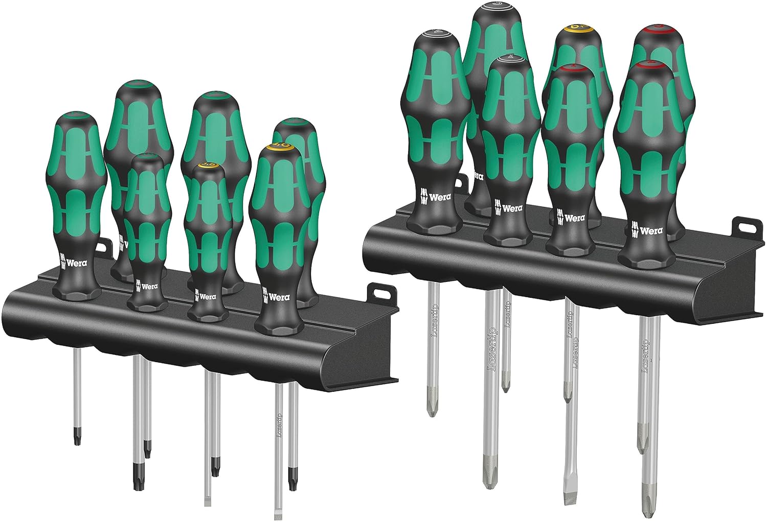
Recommended Tools for This Job


Check the Antenna or Local Harness Circuit for Opens and Shorts
If your vehicle uses separate TPMS antennas, compare the suspect corner to a known-good corner whenever possible. Similar resistance, continuity, and connector appearance can help isolate the fault. Exact specifications vary widely, so use factory data if you have it.
Useful Circuit Checks
- With power off, check continuity of the antenna signal or communication wire from the antenna connector back to the module connector.
- Check for a short to ground by measuring the circuit against chassis ground when the circuit should be isolated.
- Check for a short to power if the diagram shows the circuit should not have voltage present.
- Wiggle the harness during the test to reveal intermittent internal breaks near bends or mounting points.
A pass condition is continuity where the diagram expects it, isolation where the circuit should not be grounded or powered, and no reading changes when the harness is flexed gently. A fail condition is an open circuit, a dead short, or readings that jump around with movement.
Pay close attention to harness sections near wheel wells and underbody clips. These are common failure points because they see water, salt, vibration, and road debris.
Know the Difference Between a Wiring Fault and a Bad Wheel Sensor
Not every missing sensor signal means wiring is bad. The sensor itself may have a dead internal battery, physical damage from tire service, or the wrong programmed ID. The key is the pattern of failure.
Wiring or Antenna Is More Likely When
- The same wheel position drops out only in wet weather or after bumps.
- Two or more sensors disappear together.
- The system worked before body or wheel-well repairs.
- You find clear harness damage, corrosion, or a loose connector.
- A known-good sensor still will not communicate at that location.
Sensor Failure Is More Likely When
- Only one sensor is missing and its battery age is high.
- The valve-stem-mounted sensor was recently disturbed during tire replacement.
- A TPMS activation or tire shop tool cannot wake that specific sensor.
- Moving a known-good wheel to a different corner moves the fault with the wheel.
If you have access to a TPMS trigger tool, it can help confirm whether the wheel sensor is actually transmitting. Without one, your best DIY clue is whether the fault follows the wheel or stays with the vehicle corner.
When to Repair, Replace, or Stop and Get Professional Help
You can usually handle basic TPMS wiring issues at home if the problem is obvious: a rubbed-through wire, a loose connector, corroded terminal, or broken mounting clip that let the harness chafe. Secure routing, proper wire repair methods, and weatherproof sealing matter because these circuits live in harsh conditions.
Repair the wiring if the defect is local and accessible. Replace the connector or terminal if it has poor pin tension, heat damage, or corrosion that returns after cleaning. Replace the antenna or receiver only after power, ground, and circuit integrity have been verified. Random parts swapping gets expensive quickly with TPMS components.
Professional Help Makes Sense When
- You need factory scan-tool functions to relearn, register, or locate sensors.
- The vehicle has network communication faults involving multiple modules.
- Service information shows complex RF diagnostics or module coding.
- The fault is inside a main body harness rather than a simple branch circuit.
- You are not confident back-probing connectors or interpreting voltage-drop results.
What a Successful Inspection Should Tell You
By the end of a solid TPMS wiring inspection, you should be able to answer four questions clearly. First, is the receiver or module powered and grounded correctly? Second, are the connectors clean, dry, and tight? Third, is the local antenna or harness intact without opens, shorts, or chafing? Fourth, does the failure pattern point to the vehicle wiring or to a sensor inside the wheel?
If all electrical checks pass and the harness looks clean, the next step is usually sensor testing, sensor relearn procedures, or module-specific diagnostics. If you find obvious wiring or connector damage, repair that first, clear codes if appropriate, and confirm the system can now see all four sensors consistently.
Key Takeaways
- A flashing TPMS light usually points to a system fault, so check wiring, module power, grounds, and connectors before replacing wheel sensors.
- If multiple tires lose communication at once, suspect the TPMS receiver, fuse, power supply, ground, or shared harness instead of one bad sensor.
- Inspect wheel-well and underbody harness routing closely because water, road debris, and liner damage commonly cause TPMS antenna circuit failures.
- Use a multimeter and wiring diagram to verify stable voltage, low ground voltage drop, and continuity before condemning an antenna or control module.
- If the fault follows the wheel, the sensor is more likely bad; if it stays at the vehicle corner, the local wiring or antenna is more likely at fault.
FAQ
Can a TPMS Warning Light Be Caused by Wiring and Not the Tire Sensor?
Yes. Loose connectors, corroded terminals, damaged wheel-well wiring, failed antennas, or poor module power and ground can all cause TPMS faults even when the tire sensors themselves are still good.
What Does It Mean if the TPMS Light Flashes and Then Stays On?
That pattern usually indicates a system malfunction rather than simple low tire pressure. It commonly points to a communication, sensor, antenna, receiver, or module problem.
Do All Vehicles Have Separate TPMS Antennas?
No. Some vehicles use a central receiver only, while others use separate antennas or receivers at different body locations. Check service information for your specific model before assuming the layout.
Where Is TPMS Wiring Most Likely to Get Damaged?
Common damage points include behind fender liners, near bumper covers, along underbody harness clips, near splash shields, and in areas disturbed during suspension, wheel bearing, or body repair work.
Can I Test TPMS Wiring with a Regular Multimeter?
Yes, for basic checks like fuse condition, power supply, ground quality, continuity, and shorts. A multimeter will not directly test the radio-frequency sensor signal, but it can confirm whether the receiver and wiring are healthy.
Should I Replace the TPMS Module if I Have No Sensor Readings at All?
Not until you verify the fuse, power feed, ground circuit, and connector condition. A dead module is possible, but missing voltage or a bad ground is often the real cause.
Can Water Cause Intermittent TPMS Communication Problems?
Yes. Water intrusion can corrode connectors, change terminal contact quality, and create intermittent open or short conditions, especially in wheel-well and underbody antenna circuits.
When Should I Let a Shop Handle TPMS Diagnosis?
If your vehicle needs advanced scan-tool functions, module coding, sensor registration, or deeper network diagnostics, a professional shop with TPMS-specific tools will usually diagnose it faster and more accurately.
Need Parts for This Repair?
The right parts and supplies vary by vehicle.
Select your make and model to find compatible parts and accessories for your car.
Exact Fit
Parts that fit your make and model
Quality You Can Trust
Top brands and OEM quality options
Fast Shipping
Get the parts you need, delivered fast